Home >
Pump Control Panel
Neural

Pump Control Panel
The pump automatic control panel produced by our company is the newly developed water supply & drainage automatic control devices in our country. It could be divided into three types: direct start (0.75kw~15kw), self-coupling pressure reducing start (15kw~200kw) and Y-Star-Delta pressure reducing start (15kw~132kw). It could be divided into seven types according to different requirements: water level controlling type, pressure control type, temperature control type, time control type, air conditioner combined type, and fire-fighting type. Moreover, it could prevent for main loop’s short circuit, phrase lack, over load, over flow, the pump body leakage of special pumps and over temperature of the. Otherwise, every type above could be divided into single control type; multi main pumps and standby pump mutual control type. The main and standby mutual control type can all automatically cut off the main pump in case of the troubles, and standby pump automatically operates into stopping the pump without water. When the water level is over the preset one, the main and standby mutual control type could also have the function to warn people. So it applied for the agricultural production, urban constructions, high buildings’ water supply and drainage, fire-fighting, spraying, automatic control of pressure raising pump, the boiler’s water supply controlled by air conditioner cold-hot water cycling pump. It is also suitable for other AC motors’ control and start; therefore it is different pumps’ ideal attached products.
Code of the Type
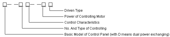
Pump Control Panel Code of the Type
1. Start Type
| Q | J | B | Z |
| Direct start | Y- Star-Delta start | Self-coupling pressure reducing start | Soft start |
2. Nos. and Type of Control Console
| 1 | 2 | 3 | 4 |
| Single | One controls two | One controls three | One controls four |
3. Control Characteristics
| L | P | T | S | C | X | B | SKD |
| Water level control | Pressure control | Temperature control | Time control | Air conditioner pump control | Fire-fighting, Spraying control | Control special for submarine pump | Dual-power control |
Working Conditions
a. The temperature around should not higher than 40℃ and lower than -5℃.
b. The surrounding air’s average temperature in 14 hours should not higher than 35℃.
c. The installation location’s altitude should not exceed 200m.
d. The air’s maximum monthly average humidity should not be bigger than 90% (average temperature equals to 25℃).
e. There should be no explosion danger medium in the air around; even there should be no gas and conductive dust in the medium that is enough to make metal corrosive and damage insulation.
f. Working voltage should be 380V±10%
Starting Type
| Starting type | Main circuit drawing | Applicable conditions and advantages |
| Direct start | 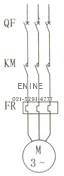 |
simple motor connections, suitable for the motors≥15kw |
| Y- Star-Delta pressure reducing start | 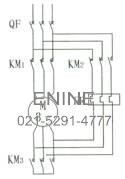 |
Small start current, suitable for the motors≥15kw |
| Self-coupling pressure reducing start | 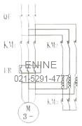 |
Small start current, simple motor connections, suitable for the motors≥15kw |
| Soft start | 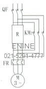 |
Start current smooth, no shock, suitable for the motors≥15kw |
Control Panel’s Type and Its Characteristics
L Type: water level control. It adopts high performance Key floating ring switch attached when it goes out our factory, so it could automatically control water supply and drainage along with the change of water level. It mainly applied in the conditions with water boxes.
P Type: pressure control. It acts through out electric connector gauge or pressure switch as transmission signal to automatically open and close the pumps according to pipeline network’ pressure difference tested. This type is also suitable for button remote control type. It mainly applied in the system of living water supply and fire-fighting pressure sustaining.
T Type: temperature control. It acts through temperature transducer as testing component, and attaching with temperature controller to open and close pumps according to preset temperature range. It mainly applied in the system of constant temperature and heat exchanging.
S Type: time control. This type acts through adopting computer clock controller, according to the customers’ time requirements to control the pump’s open and close. It mainly applied in the conditions of regular intermittent water supply.
C Type: control special for air conditioner. This type is designed specially for air conditioner pump, The control center operates the pump’s open so as to realize the linkage between the air conditioner pump and air conditioner unit. Water pump outputs a control connector to let the cooling unit open, realizing the program that must open water pump first and then open the air conditioner unit, so as to ensuring the safe running of air conditioner system.
X Type: control special for fire fighting. This type is designed according to the national fire-fighting regulations. Any of the following ways could start the fire-fighting and spraying pump: manual operation of panel’s faceplate, button start of fire hydrant, start of pressure switch and start of fire-fighting center DC24V. And also the various open-close of different pumps transferred to the fire-fighting center. If customer need dual power automatic cut off device and fire-fighting pump’s timely check function, please indicate in the order.
W Type: control special for submarine sewage pump. This type is designed according to submarine sewage’s special working location. It adopts floating ball switch and electric to realize opening the pump at high water level and closing the pump at low water level. Even it could prevent the pump body for leakage and stator winding’s temperature is too high.
Various Control Panels’ Control and Connectors’ connecting
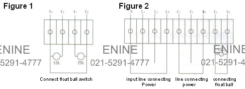
1. Water Level Control
I adopts two connector floating ball, referring to the Figure 1. If adopt the floating ball, there shall need only one, whose connecting is making the switch connected with connector Y1, Y2, referring to Figure 2.
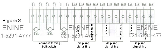
2. The Water Level Standby Pump is put into Operation Automatically
If adopt the floating ball, there shall need only one, referring to Figure 3.
If adopt the floating ball, there shall need only two, whose connecting is making connector Y1, Y3 connected shortly first, second making the common floating ball of starting pump and stopping pump connected with connector Y1, Y2, then making the standby pump’s floating ball connected with connector Y1, Y4. If this type control panel is used to control other types pump, in other words, the pump without any leakage or temperature signal, so there shall need the connectors of leakage and temperature signal overhung, not connected with any circuit, or it will not work normally.
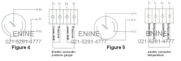
3. Pressure Control Type
Transducer normally choose the electric connector pressure gauge (such as YX series) presetting the upper and lower limits, or choose two electric connector pressure gauge or pressure relay of that upper and lower limits are independent. When pressure low to the lower limit, P0 connects with P1, then the pump starts working; when the pressure raise to the upper limit, P0 connects with P2, then the pump stops working. Referring to Figure 4.
4. Temperature Control Type
Transducer normally adopts pressure gauge to set the electric connector temperature gauge of the upper and lower limits or choose other temperature regulator. When temperature reaches the upper limit, T0 connects with T2, and then the pump start working; when temperature reaches the lower limit, T0 connects with T1, then the pump stop working. Referring to Figure 5.
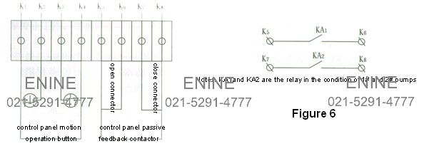
5. Air Conditioner Combined Control Type
If need operation along with the movement, there shall make K1 and K2 put close (stop) button, K3 and K4 put open (start) button. If don’t need operation along with the movement, first make K1 and K2 short circuit, and then K3 and K4 cut off, so the control panel shall be controlled by control panel plate buttons. If need open the water pump first, and then open the air conditioner unit, there shall make K5 and K6 be into the loop of air conditioner unit in series. Referring to Figure 6.
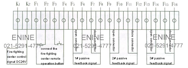
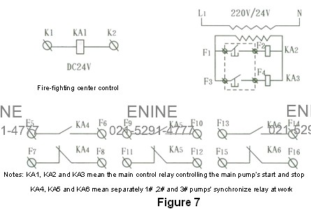
6. Fire-fighting and Spraying Pump
The Figure 7 shows the pump open-close connectors of fire-fighting controller transfers to various distribution pumps, or remote control button signal of fire-fighting controller transfers to fire-fighting center.
Control Panel’s Fife-fighting and spraying Principle Figures
Figure of Fire-fighting Automatic Control Principle as follows:
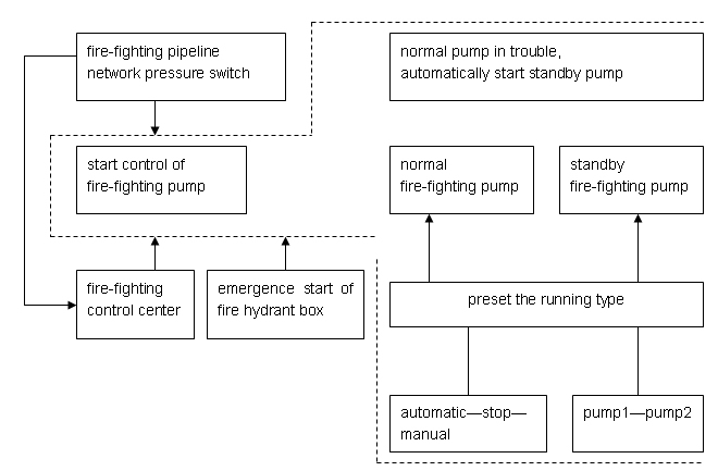
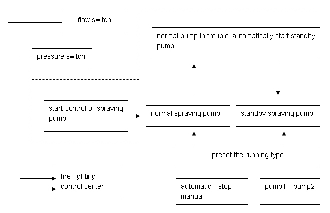
Figure of Spraying Pump Automatic Control Principle as follows:
Control Panel’s External Installation
1. Magnetic Floating Ball Switch Control
(1) Water Level Control: There should choose one magnetic switch.
a. water supply working condition (adopting floating ball close connectors)
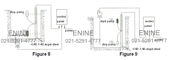
You should make the two down-leads connecting floating ball switch close connectors connect with Y1 and Y2. Then when it is filled with water, the floating ball raise to the white ball position naturally, the close connectors cut off, so the pump stop working; when the water level falls to the position of starting the pump (referring to black ball in figure 8), the open connectors get connected, so the pump starts working.
b. water drainage working condition (adopts floating ball open connectors)
There should make the two down-leads of floating ball connect with Y1 and Y2. When the water level raising to be full, the floating ball get up naturally, until to the position of starting pump (referring to black ball in figure 8), the open connectors get connected, so the pump starts working. And then water level begins to fall, until falls to the position of stopping the pump (referring to white ball in figure 9), floating ball open connectors cut off, so the pump stop working.
(2) Fixed Water Level Standby Pump Puts into Work Automatically
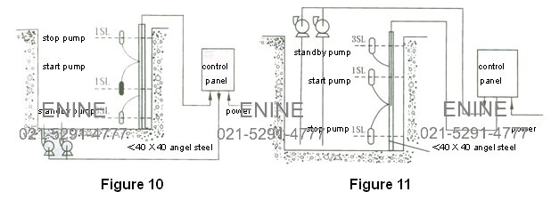
There should choose two floating ball switches, in other words, stopping pump and starting pump share one floating ball 1SL, and another floating ball 3SL controls the standby pump.
a. water supply working condition (adopting floating ball close connectors)
First make the Y1 and Y3 in the control panel connect shortly, then make the two down-leads of the floating ball 1SL shared by starting pump and stopping pump connect with Y1 and Y2, and make the close connectors of floating ball 3SL of standby pump connect with Y1 and Y4. When the water level falls to the position of starting pump (referring to black ball of 1SL), the main pump starts to work. If the flow used is bigger than the supply flow of the main pump (or the main pump is in trouble), water level will falls continuously until the position of standby pump’s starting (referring to floating ball of 3SL), the standby pump will be put into operation. In other words, the main pump and standby pump will work at the same time. And when the water level raises to the position of stopping pump (referring to white ball of 1SL), both the main pump and stand by pump will stop working. Referring to Figure10.
b. water drainage working condition (adopts floating ball open connectors)
First make the Y1 and Y3 connect in short, then make the two down-leads of the floating ball 1SL shared by starting pump and stopping pump connect with Y1 and Y2, and make the close connectors of floating ball 3SL of standby pump connect with Y1 and Y4. So with the water level raises or falls, or the change of floating ball switch position, the water pump shall open, close or put standby pump into operation. Referring to Figure 11.
2. Mercury Floating Ball Switch Control
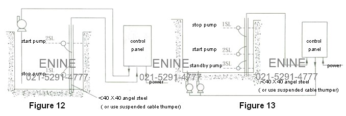
(1) Water Level Control: It adopts two floating ball switches; separately control the pump’s open and close. Stopping floating ball 1SL connects Y1 and Y2, and Starting pump floating ball 2SL connects Y1 and Y3.
a. Water drainage working condition (adopting floating ball open connectors), referring to Figure 12
b. Water supply working condition (adopting floating ball close connectors), it need only exchange the position of floating ball switches in the Figure 12, in other words, put stopping pump floating ball 1SL up and starting pump floating ball down.
(2) Fixed Water Level Standby Pump Puts into Work Automatically
There should adopt three floating ball switches, separately control the water pump’s starting, stopping or the standby pump’s putting into operation. 1SL connects with Y2, 2SL connects with Y1and Y3 and 3SL connects with Y1and Y4.
a. Water supply working condition (adopting floating ball close connectors), referring to Figure 13.
b. Water drainage working condition (adopting floating ball open connectors), it need only exchange the position of 1SL and 3SL. In other words, put the stopping pump floating ball 1SL lowest, the standby pump floating ball 3SL up, and the starting pump floating ball 2SL at the medium position.
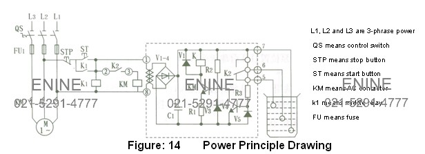
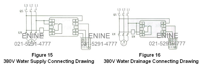
3. Electrode Control
It adopts water level controller and electrode probe to control the water level of heat water and corrosive liquid. Because the electrode probe is made of stainless steel pipes, it could control the water level of any liquid accurately. Referring to Figure 14, 15, 16.
Application & Notice
1. When install the connecting of the control panel, must according to the meanings of different letters and make the connecting in accordance with the connector figures; when finishing the installation, should check the connecting carefully, and check the actual capacity of the motor it controlled whether in accordance with the capacity controlled by the product. If not, please refer to all the parameters in the parameter table, then set the current again, including the current motion value of the time exchanging device, the setting value of protection extending and the setting value of the heat relay.
2. Manual operation: First supply the power, the power indicator light is on, put the function switch on the manual operation position, open the switches of the distribution pumps (the switch is in accordance with every pump unit), put the pump working chosen switches on the requiring position (in other word, choose the main pump and standby pump). Put the starting button, the motor starts to start working, and then the starting indicator light is on. When the starting current falls to the 1.5 times of rated current, the motor changes to full pressure running condition, and then the working indicator light is on. If put the stopping button, the motor stops working, the stopping indicator light is on. When starting, if find that the current exchanging times if not right, should take on-spot adjustment according to the actual conditions. If some control circuit uses time relay to exchange, should know the time required through observing the current gauge that from the motor needs from its starting to the current falls to the 1.5 times of the rated current, and then reset the time relay’s setting value.
The choice of working exchanging switches: If the system is 2-pump system, could choose “1# as the main pump, 2# as the standby pump” or choose “2# as the main pump, 1# as the standby pump”; if the system is 3-pump system, could choose “1# and 2# as the main pump, 3# as the standby pump” or choose “1# and 3# as the main pump, 2# as the standby pump” and choose “2# and 3# as the main pump, 1# as thestandby pump”; if the system is 4-[ump system, could choose “1#, 2#, 3# as the main pump, 4# as the standby pump” or others.
3. Automatic operation: Put on the automatic air switch; choose the main pumps and standby pumps. Put the function switch on the automatic position, put the different distribution pump, and then the pump controller will automatically start the main pump or the standby pump or stop the water pump’s running.
4. Troubles: When the water pump is in trouble, if find the motor is over load, lacking phrase, the temperature is too high, and the pump is leakage, this type control panel will automatically cut off the motor’s power, stop the motor working, even indicate different troubles. If adopting the standby type control panel, when any main pump unit is in trouble, the standby pump will automatically put into operation.
5. In the process of the motor’s starting, the operator should check carefully whether the control panel is into the operation after its starting, in order to avoid that the starting time is too long to arouse the motor’s damage. As to the unusual control panel such as controlling the fire-fighting or spraying pump, etc. should take timely starting and checking.
6. The autotransformer of permits twice continuous starting, and any starting needs 15S, the time between the starting. The starting time of adjusts through the time relay according to different motor powers. The extending time’s adjustable range is 15~20S.
Check before Installation & Commissioning
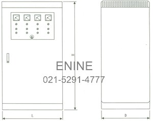
1. Before installing the installation devices, should according to the external dimensions and refer to the installation introduction, install some fixing devices on the wall and foundation channel beams on the floor.
2. Taking the outside circuit connecting according to design drawing. But you must remove off the dust and other remains in the panel after the installation.
3. You should take the following checks before putting into operation.
(1) Check the first connecting and second connecting in the panel whether right of wrong, and the various parts standards are whether in accordance with the requirements or not.
(2) Check the air switch, contactor, heat relay and other parts whether work flexibly or have block.
(3) Check whether there are other things in the panel and the fixing screws loosen or worn.
(4) Taking the necessary electric test and resistor insulation test according to the regulations and so on.
Answers to Common Questions
1. The reversion of the motor
Description of the trouble: The head of the pump can not reach the rated head, or the discharge flow is too small, or the current of the motor is smaller compared to rated current.
Resolution: Adjust any two wire lines’ connecting positions of the three ones in the panel, in other words, adjust the phrase sequence.
2. The main return circuit has current while the secondary return circuit does not have the current.
Description of the trouble: After supplying the power, the indicator light is not on, the control in the panel is out of control.
Resolution: ①for there is the protection of secondary short circuit through a mini switch. So if don not put the
mini switch, the secondary return circuit will not supply the power.
②The control return of the panel is divided into two types of 380V &220V, and it is 220V. So check whether the zero line is put into or connected tightly.
3. The water level in the water supply & drainage system, the water level controlled by only one floating ball is not accurate
Description of the trouble: Both the panel and the floating ball have installed, the water level has not set yet, but the control panel has automatically opened or closed.
Resolution: If using only one floating ball to control the water level, that may be because of the differential
water level is too big to control it accurately. In this case, you should use two floating balls to
control it (one floating ball at the higher water level while the other at the lower). You could
refer to the Figure 12 to install.
4. The water level control installed counter
Description of the trouble: When supplying the water (draining), the water box is already full (empty); the panel just start to work, there is no water in the water pool (the water pool is already full). Overall, the control panel’s stopping and using counter.
Resolution: You should according to the floating ball switch’s introduction; using close to supply water while using open to drain water. Connect the floating ball connecting again.
5. Star-Delta pressure reducing priming motor’s connecting is wrong
Description of the trouble: When the motor can start normally, but it is put into operation, it stops suddenly, or the air switch is cut off.
Resolution: ①When the motor is put into operation, it stops suddenly. You should check the connecting
between the motor connector and the control panel connector compared with the circuit
drawing. After the checking, install the connecting again.
②When the motor is put into operation, the air switch is cut off. You should check whether
the connecting sheet copper of the motor connector is dismantled fully and the connecting
cable has been worn or not.
6. Pressure reducing start moment is not enough
Description of the trouble: When the pressure reducing box starts, the motor can not run due to its moment is not enough.
Resolution: ①Check if the motor has phrase lack
②If it is the heavy load start, should adjust the transformer’s 65% pumping head to 80% pumping
head. (55% normally)
7. If adopting one main pump & one standby pump type control panel ≤15KW, unable to adjust to the standby pump when the main pump is in trouble
Description of the trouble: When testing the control panel’s adjusting function, if dismantle any line of the main control AC contactor loop of the main pump, the control panel cannot adjust the main pump to the standby pump.
Resolution: When adopting the one main pump & one standby pump type control panel ≤15KW, the control panel‘s trouble signal adopts the open contactor point of heat relay. So when testing the trouble adjusting, because of lack of heat relay’s “97” and “98“. Therefore, this is a man-made trouble in the testing. (remarks: because of different control requirements, for detailed information, please refer to the notes of the drawing).
Box or Panel’s External Dimensions Figures
Parameter Table
1. Direct Start Type
| No. | Power (KW) |
Current (A) |
Panel Body (H X L XD) | |||
| One controls One | One controls Two | One controls Three | One controls Four | |||
| 1 | 0.75 | 1.5 | 400 X300 X200 | 500 X400 X200 | 600 X400 X200 | 800 X600 X250 |
| 2 | 1.1 | 2.2 | 400 X300 X200 | 500 X400 X200 | 600 X400 X200 | 800 X600 X250 |
| 3 | 1.5 | 3 | 400 X300 X200 | 500 X400 X200 | 600 X400 X200 | 800 X600 X250 |
| 4 | 2.2 | 4.4 | 400 X300 X200 | 500 X400 X200 | 600 X400 X200 | 800 X600 X250 |
| 5 | 3 | 6 | 400 X300 X200 | 500 X400 X200 | 600 X400 X200 | 800 X600 X250 |
| 6 | 4 | 8 | 400 X300 X200 | 500 X400 X200 | 600 X400 X200 | 800 X600 X250 |
| 7 | 5.5 | 11 | 400 X300 X200 | 500 X400 X200 | 800 X600 X250 | 800 X600 X250 |
| 8 | 7.5 | 15 | 400 X300 X200 | 500 X400 X200 | 800 X600 X250 | 800 X600 X250 |
| 9 | 11 | 22 | 500 X400 X200 | 600 X400 X200 | 800 X600 X250 | 800 X600 X250 |
| 10 | 15 | 30 | 500 X400 X200 | 600 X400 X200 | 800 X600 X250 | 800 X600 X250 |
2. Pressure Reducing Start, Soft Start Control Panel
| No. | Power (KW) |
Current (A) |
Panel Body (H X L XD) | |||
| One controls One | One controls Two | One controls Three | One controls Four | |||
| 1 | 11 | 22 | 1200 X 500 X 350 | 1400 X 600 X 400 | 1700 X700X 450 | 2000X1000X550 |
| 2 | 15 | 30 | 1200 X 500 X 350 | 1400 X 600 X 400 | 1700 X700X 450 | 2000X1000X550 |
| 3 | 18.5 | 37 | 1200 X 500 X 350 | 1400 X 600 X 400 | 1700 X700X 450 | 2000X1000X550 |
| 4 | 22 | 44 | 1400 X 600 X 400 | 1400 X 600 X 400 | 1800 X800X 500 | 2200X1200X600 |
| 5 | 30 | 60 | 1400 X 600 X 400 | 1400 X 600 X 400 | 1800 X800X 500 | 2200X1200X600 |
| 6 | 37 | 74 | 1400 X 600 X 400 | 1400 X 600 X 400 | 2000X1000X550 | 2200X1200X600 |
| 7 | 45 | 90 | 1400 X 600 X 400 | 1700 X 700 X 450 | 2000X1000X550 | 2200X1200X600 |
| 8 | 55 | 140 | 1400 X 600 X 400 | 1700 X 700 X 450 | 2000X1000X550 | 2200X1200X600 |
| 9 | 75 | 150 | 1400 X 600 X 400 | 1800 X 800 X 500 | 2000X1000X550 | 2200X1200X600 |
| 10 | 90 | 180 | 1700 X 700 X 450 | 1800 X 800 X 500 | 2200X1200X600 | 2200X1200X600 |
| 11 | 110 | 220 | 1800 X 800 X 500 | 2000 X1000 X 550 | 2200X1200X600 | 2200X1500X600 |
| 12 | 132 | 260 | 1800 X 800 X 500 | 2000 X1000 X 550 | 2200X1200X600 | 2200X1500X600 |
| 13 | 160 | 320 | 1800 X 800 X 500 | 2000 X1000 X 550 | 2200X1200X600 | 2200X1500X600 |
3. Star-Delta Pressure Reducing Start
| No. | Power (KW) |
Current (A) |
Panel Body (H X L XD) | |||
| One controls One | One controls Two | One controls Three | One controls Four | |||
| 1 | 11 | 22 | 800 X600 X250 | 1400 X 600 X 400 | 1600 X600X 400 | 1700 X700X 450 |
| 2 | 15 | 30 | 800 X600 X250 | 1400 X 600 X 400 | 1600 X600X 400 | 1700 X700X 450 |
| 3 | 18.5 | 37 | 800 X600 X250 | 1400 X 600 X 400 | 1600 X600X 400 | 1700 X700X 450 |
| 4 | 22 | 44 | 1400 X 600 X 400 | 1400 X 600 X 400 | 1700X700 X 450 | 1800 X800X 500 |
| 5 | 30 | 60 | 1400 X 600 X 400 | 1400 X 600 X 400 | 1700X700 X 450 | 1800 X800X 500 |
| 6 | 37 | 74 | 1400 X 600 X 400 | 1400 X 600 X 400 | 1800X800 X 500 | 2000X1000X550 |
| 7 | 45 | 90 | 1400 X 600 X 400 | 1700 X 700 X 450 | 1800X800 X 500 | 2000X1000X550 |
| 8 | 55 | 140 | 1400 X 600 X 400 | 1700 X 700 X 450 | 1800X800 X 500 | 2000X1000X550 |
| 9 | 75 | 150 | 1400 X 600 X 400 | 1700 X 700 X 450 | 2000X1200X550 | 2000X1200X550 |